Ring Rewards: A HealthKit Linked Candy Dispenser
Welcome to Ring Rewards!
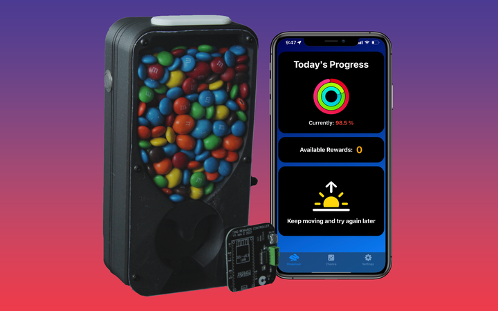
This is Ring Rewards, an IOS app that syncs your activity data using Apple’s HealthKit, and uses that to determine if you’ve earned a candy reward. The full video describing the design and build process is available here:
This project was my first personal end-to-end product which incorporated software, electronics and mechanical design. I was able to learn many new skills over the course of this project including IOS development, PCB prototpying and design, and how to perform a scaled beta test.
This is the culmination of about a project I've been working on in the background (very much on and off again) for over a year. It started as a 1 week design sprint during Mark Rober's Creative Engineering class on Studio, but ended up being a project that inspired me to learn how to make a PCB, how to program and release an IOS app with Swift and much much more.
The IOS app to accompany this device is available on the App Store worldwide, and the PCB Gerber files along with Arduino code are available on the linked GitHub repo.

The dispenser itself was designed with peanut covered MnMs in mind (who's non-uniform proportions really messed with my head for a while when focusing on one idea…), but the design should be relatively easily adapted to any similar sized candy.
In addition, I would encourage anyone who's interested in a fun project to try and design their own candy dispenser mechanics to go along with my app. It's a great intro project and will be a fun piece to have around.
All models can be found on my printables.com page here: https://www.printables.com/model/229330-apple-fitness-candy-dispenser-ring-rewards
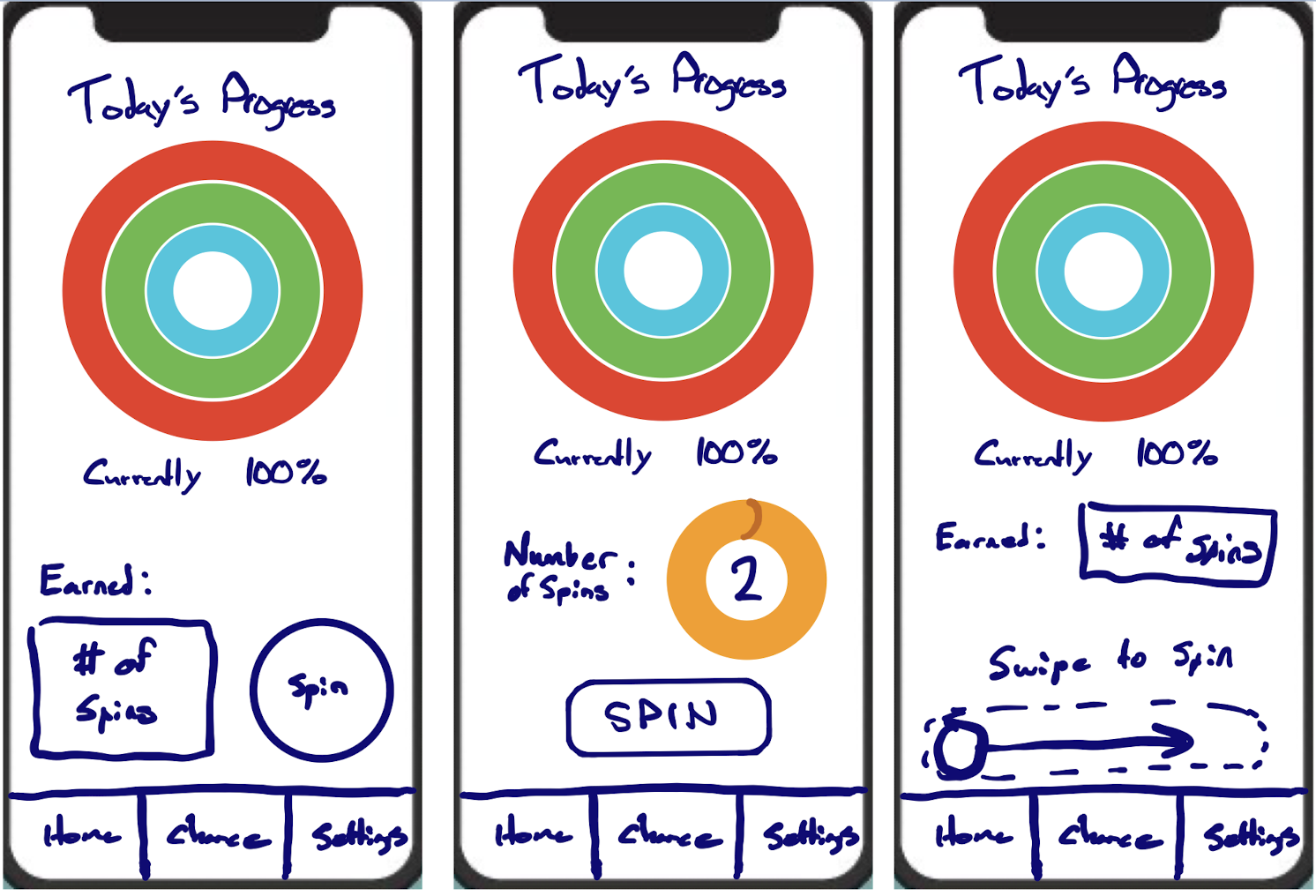
The app design process started with some simple UI sketches and ended up with my first ever IOS app, which dare-I-say actually works!
Build Instructions/BOM:
| # | Part | QTY | Link (if applicable) | Material |
|---|---|---|---|---|
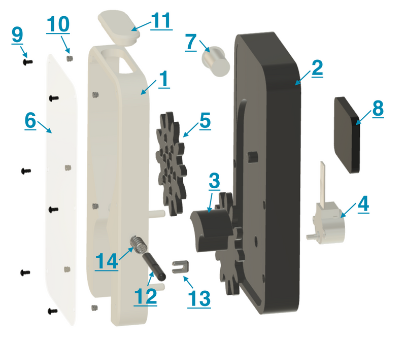
| 1 | Front Body Panel | 1 | Printed Part | PLA |
| 2 | Rear Body Panel | 1 | Printed Part | PLA |
| 3 | Primary Dispenser Knob/Gear | 1 | Printer Part | PLA |
| 4 | 28BYJ-48 ULN2003 5V Stepper Motor | 1 | Find the cheapest/easiest you can. They're everywhere | N/A |
| 5 | Secondary Dispenser Knob/Gear | 1 | Printed Part | PLA |
| 6 | Acrylic Panel | 1 | Laser Cut/Hand Cut | Acrylic |
| 7 | 16mm Latching Push Button Switch | 1 | Find the cheapest/easiest you can. They're everywhere | N/A |
| 8 | Electronics PCB | 1 | Order From these files or use breadboard. | N/A |
| 9 | M3x0.5x6mm Screws | 6 | McMaster | 18-8 |
| 10 | M3 Heat Set Inserts | 6 | McMaster | Brass |
| 11 | Loading Cap | 1 | Printed Part | TPU |
| 12 | Jam Clearing Rod | 1 | Printed Part | PLA |
| 13 | Jam Rod Retainer | 1 | Printed Part | PLA/PETG |
| 14 | Jam Rod Spring | 1 | 8-10mm ID, >20mm free length MIN | Misc. Metal |
| 15 | Command Strips | 5 | Velcro style 2-part command steps or similar | Adhesive |
| 16 | Superglue | N/A | Superglue or desired permanent adhesive | N/A |
- Print all plastic components listed above in your desired color-ways (go wild!) and post-process as needed. It's a good idea to ream out the printed holes, especially for the jam clearing rod. Ensure all ordered components are on-hand before assembly.
- Insert stepper motor (item 4) into the corresponding area on item 2. A *light tap* with a mallet may be required.
- Insert the power button (item 7) into item 2.
- Assemble primary gear (item 3) onto item 2-4 assembly (press firmly to ensure proper engagement.
- Insert secondary gear (item 5) onto item 2 post. If desired, lightly mushroom the post after assembly using heat, but this is not required for function and may hamper cleaning efforts.
- Attach PCB (item 8) using a command strip cut to size. Allows for easy servicing. Ensure power micro-usb connection is facing downwards. Solder connection to power button and plug-in the stepper motor.
- Press in the heat set inserts (item 10) and allow to cool.
- Depending on if you are right or left handed, choose a side to insert the jam clearing rod. Insert spring (item 14) into item 1 slot, then gently feed pusher rod (item 12) through the spring/slot and pin using item 13. Ensure function of mechanism before continuing.
- If using a laser cut acrylic sheet, proceed. If cutting by hand, print the attached template (ensure your print scaling works properly…measure!!). Then glue to acrylic and cut using scissors. Sand edges as needed.
- Remove protective film and instal acrylic panel (item 6). Secure using the M3 screws (item 9).
- Bond Item 1 and Item 2 assemblies together using your preferred adhesive, using the alignment pegs of item 1 as a guide. Ensure glue coverage on the top section of the dispenser!
- Allow glue to fully cure, cleaning excess as needed. Once cured (and you're happy enough to EAT off of it…I'm not responsible for any poisoning due to this project…); add your favorite candy!
- Insert cap (item 11) to secure your food from prying fingers.
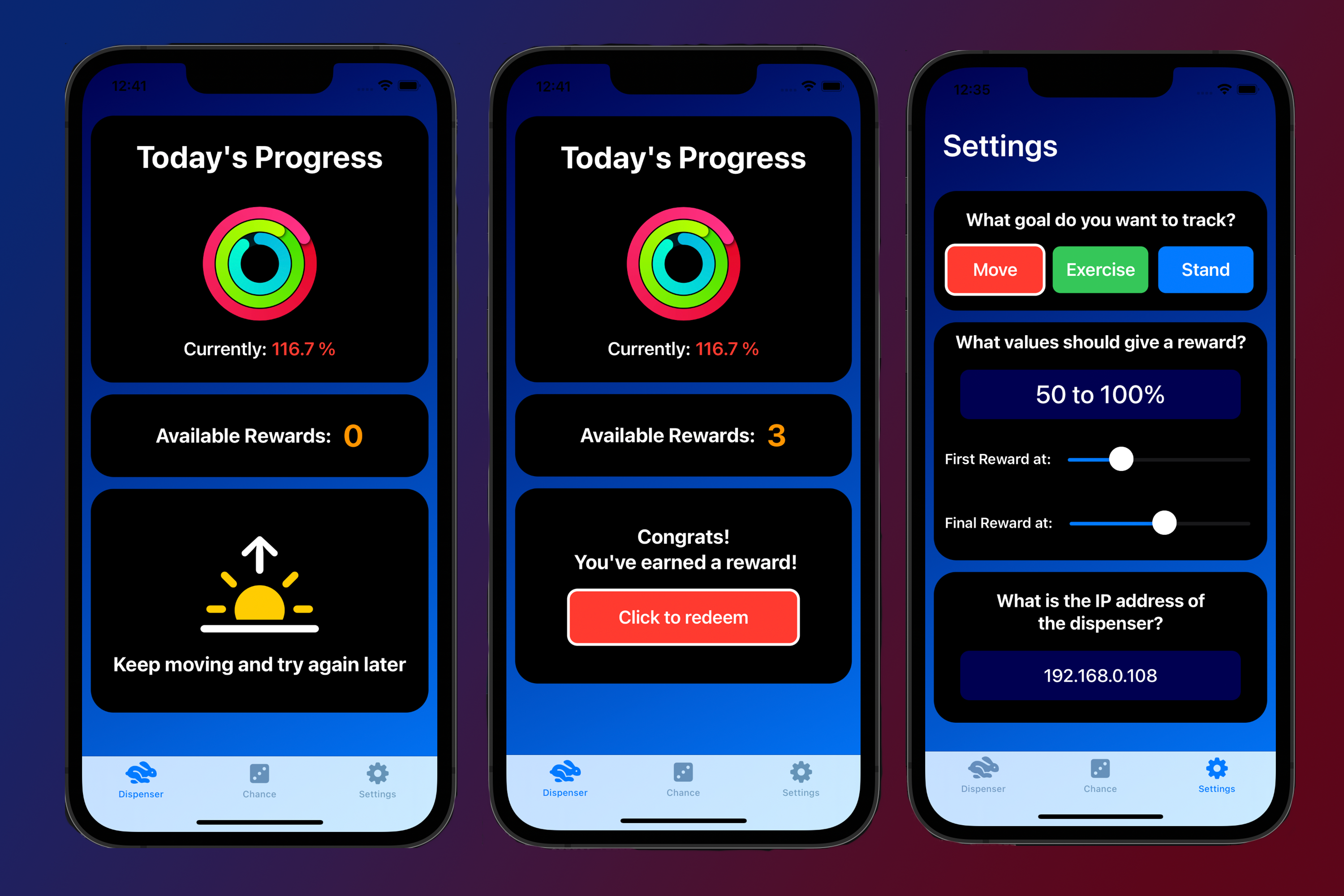
- Download and update the Arduino code with your home wifi network SSID and password. During the initial setup, make sure you flash the arudino code onto your board and run it with the console open so you can read the IP address it connects to. This address should then be entered into the settings section of the iPhone app.
- Get moving so you can earn some rewards!
This project was a ton of fun to build and test and build and test and build… you get the idea. I learned so much and it’s inspired me to start a couple new projects which you’ll hopefully be seeing soon! If you choose to make your own dispenser with the linked parts I hope you enjoy it too!
Iain Zwiebel
Biomedical Engineer
Iain Zwiebel is a Biomedical Engineer committed to creating positive change in the world through human centered design, particularly in the health sector.